
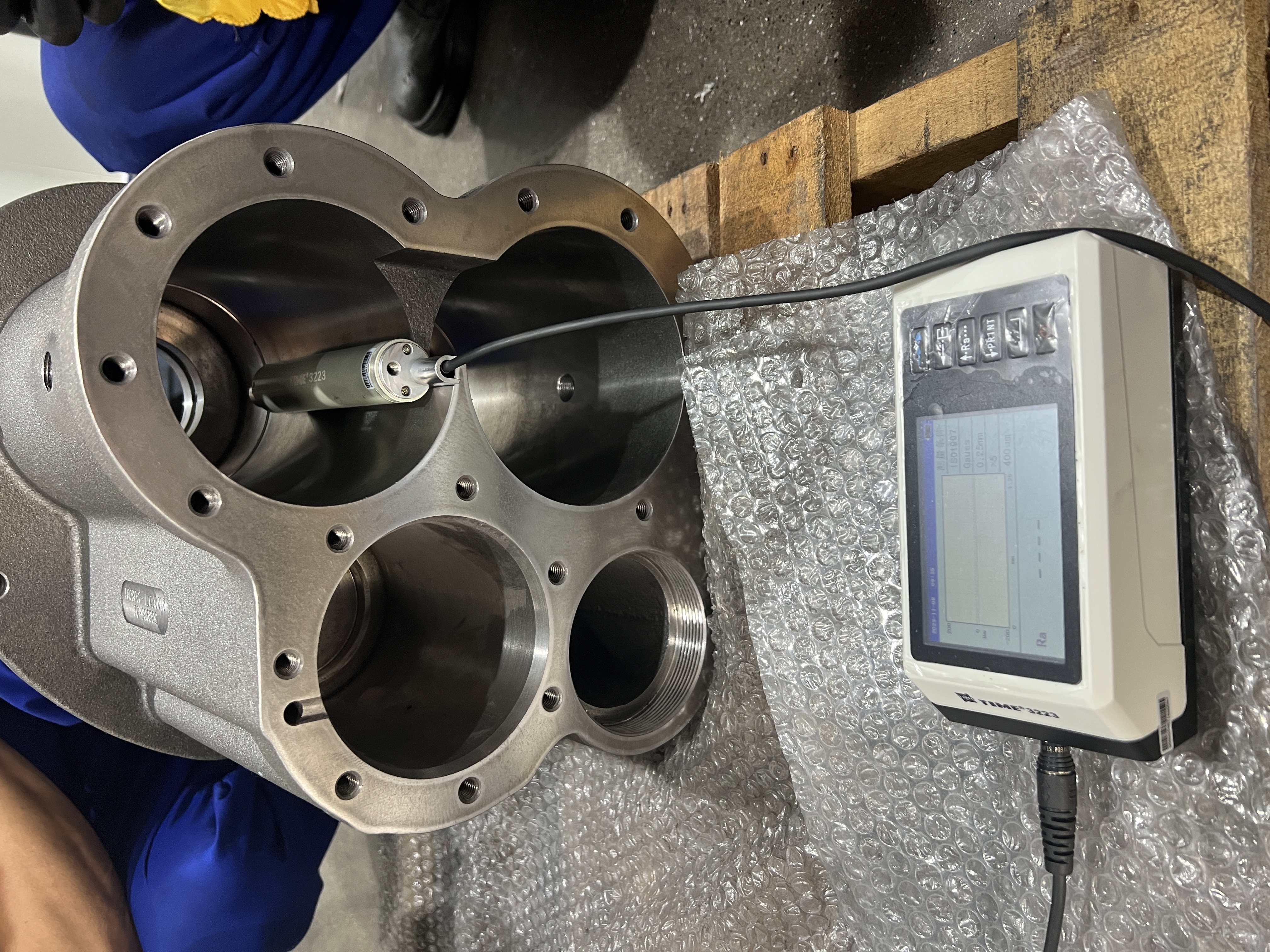
Application of circular drive roughness tester.
Circular drive roughness meters (such as rotary or circular scanning roughness meters) are designed to meet the needs of curved surface measurement and have unique advantages in the surface roughness detection of tubular workpieces. The following are its specific applications and technical points:
1. Application scenarios
Pipeline inner wall/outer wall detection:
Measure the roughness of the inner wall of oil pipelines, hydraulic pipes, heat exchanger tubes, etc., and evaluate fluid resistance, corrosion risk or coating uniformity.
Surface evaluation of shaft parts:
Detect the processing quality of cylindrical surfaces such as drive shafts and bearing seats to ensure assembly accuracy and friction performance.
Medical catheters and precision pipes:
Perform high-precision roughness analysis on the inner surface of minimally invasive surgical catheters and fine metal tubes to avoid biological contamination or fluid retention.
3D printed tubular parts quality control:
Detect the surface uniformity after printing layer patterns or post-processing (polishing, sandblasting).
2. Technical advantages
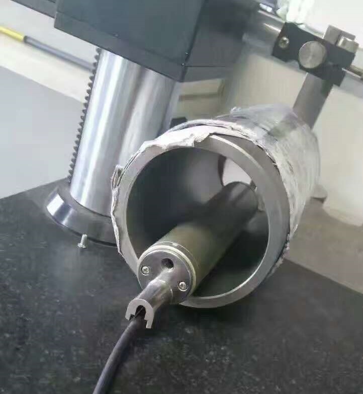
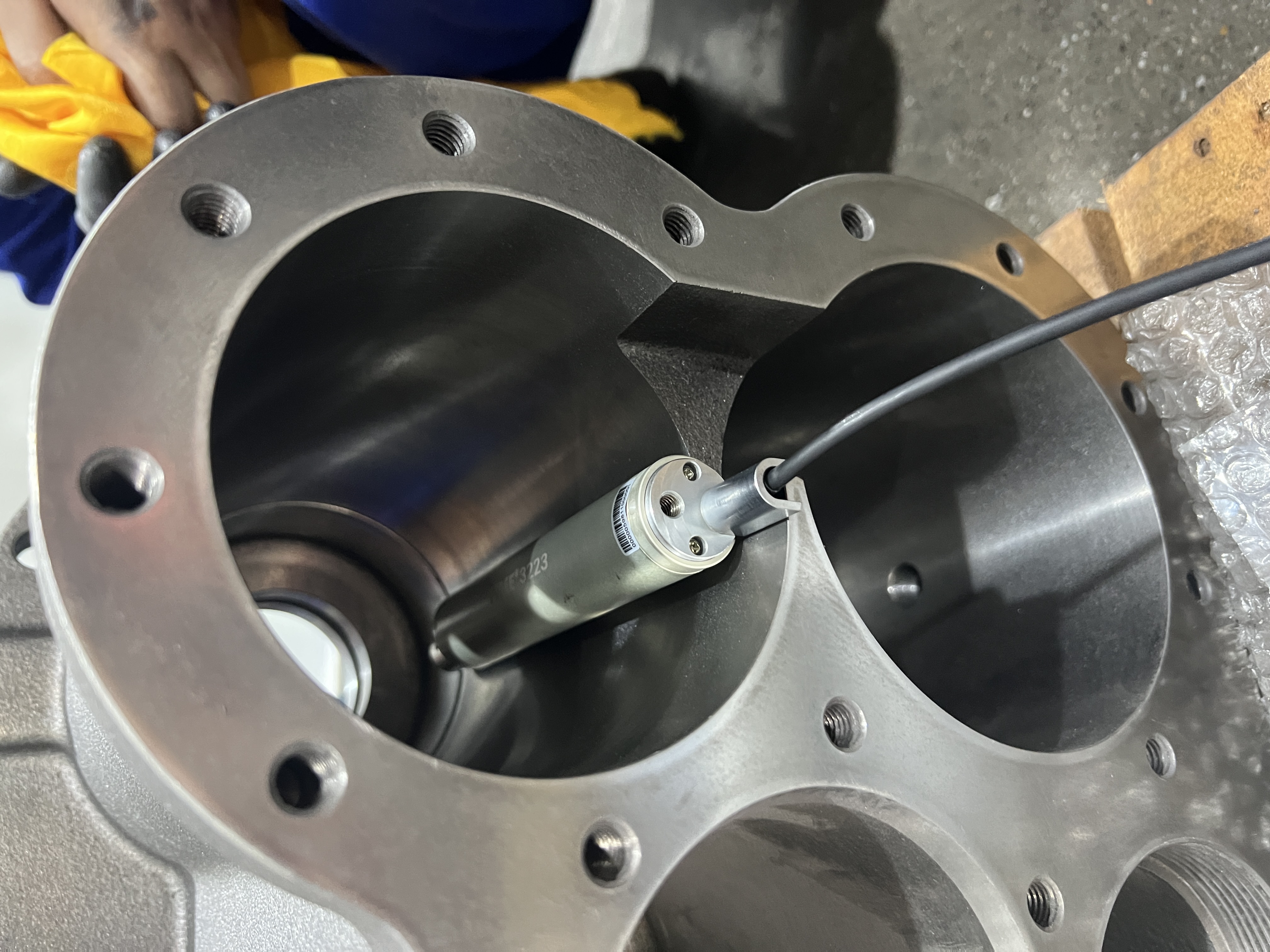
Surface adaptation:
The circular drive probe fits the tubular surface through rotation or arc scanning, avoiding the measurement error caused by curvature of traditional linear probes.
Multi-angle data acquisition:
Continuous measurement along the circumferential direction to capture the roughness differences in the axial and circumferential directions (such as the directional effects of turning and grinding textures).
High precision and repeatability:
Use constant pressure contact or non-contact (such as white light interferometry) technology to ensure stable probe pressure and reduce human interference.
Portability and flexibility:
Some handheld designs can adapt to pipes of different diameters (such as with magnetic bases or adjustable brackets), suitable for on-site inspection.
3. Key points of measurement operation
Surface pretreatment:
Clean the area to be measured, remove oil, oxide layer or burrs, and avoid interference with probe contact.
Calibration and parameter setting:
Calibrate the instrument according to the curvature radius of the pipe to compensate for the geometric error caused by the curved surface.
Set the appropriate scanning length (such as 4mm or 5mm), evaluation length (including 5 sampling lengths) and filter type (Gaussian filtering is commonly used).
Probe selection and fixation:
For small diameter pipes (<50mm), micro probes or special sensors for inner walls should be used.
For outer wall measurement, magnetic clamps or flexible fixtures can be used to ensure that the probe fits stably.
Data acquisition and analysis:
Measurement at multiple points along the axial and circumferential directions to generate a 3D roughness profile.
Key parameters: Ra (arithmetic mean roughness), Rz (maximum height), Rsm (average width of profile unit), etc.
4. Typical problems and solutions
Measurement distortion caused by curvature:
Use a curvature compensation algorithm or select a sensor with a small probe contact area (such as a 2μm radius diamond probe).
Inner wall measurement blind area:
For extremely small diameter pipes (such as <5mm), use fiber optic probes or optical coherence tomography (OCT) technology instead of contact measurement.
Vibration interference:
In a workshop environment, use a shock-proof bracket or a short sampling length (such as 0.8mm) to improve the signal-to-noise ratio.
Poor data consistency:
Take the average value through multiple measurements, or use an automatic positioning system to reduce human operation deviation.
5. Industry standards and cases
Standard references:
ISO 4287 (definition of surface roughness parameters)
ASME B46.1 (surface texture measurement specification)
GB/T 1031 (domestic roughness assessment standard)
Actual cases:
Petroleum pipeline anti-corrosion coating inspection: through inner wall roughness analysis (Ra≤0.8μm), ensure that the coating adhesion meets the standard.
Automobile brake pipe inspection: control the outer wall Ra of the hydraulic pipe within the range of 0.4-1.6μm to reduce the flow resistance of the brake fluid.
6. Development trend
Intelligent integration:
Combined with industrial robots, fully automatic online inspection of pipe fittings (such as automobile exhaust pipe production line) is realized.
Multimodal fusion:
Combined with white light interferometer and circular drive technology, roughness and three-dimensional morphology data are obtained simultaneously.
AI data analysis:
Use machine learning to identify processing defects (such as vibration marks and burns) and associate process parameter optimization.
By properly selecting a circular drive roughness tester and operating it in a standardized manner, the problem of measuring the surface roughness of tubular workpieces can be efficiently solved, significantly improving manufacturing quality and product reliability.
-
Phone: +86-10-62966798
Fax: +86-10-62980728
Email: export@timegroupndt.com.cn


