
The Breakthrough Application of Ultrasonic Hardness Testers in Laser Cladding Hardness Testing
A Technological Revolution Achieving Precise Measurement of Minimally Damaged Gradient Materials
Industry Pain Points in Laser Cladding Hardness Testing
Laser cladding technology, which deposits alloy powders onto substrate surfaces to form high-performance coatings (such as nickel-based alloys and tungsten carbide coatings), is widely used in areas such as aircraft engine blade repair and hydraulic plunger strengthening. However, traditional hardness testing methods face two major challenges:
1). Destructive Risk: Rockwell/Vickers hardness testers require penetration into the coating surface, which can easily cause cracking or delamination of thin cladding layers (0.1-0.5 mm);
2). Gradient Failure: The hardness gradient from the cladding layer to the substrate (e.g., surface HRC 62 → substrate HRC 25) makes traditional single-point measurement incapable of continuously characterizing the transition zone.
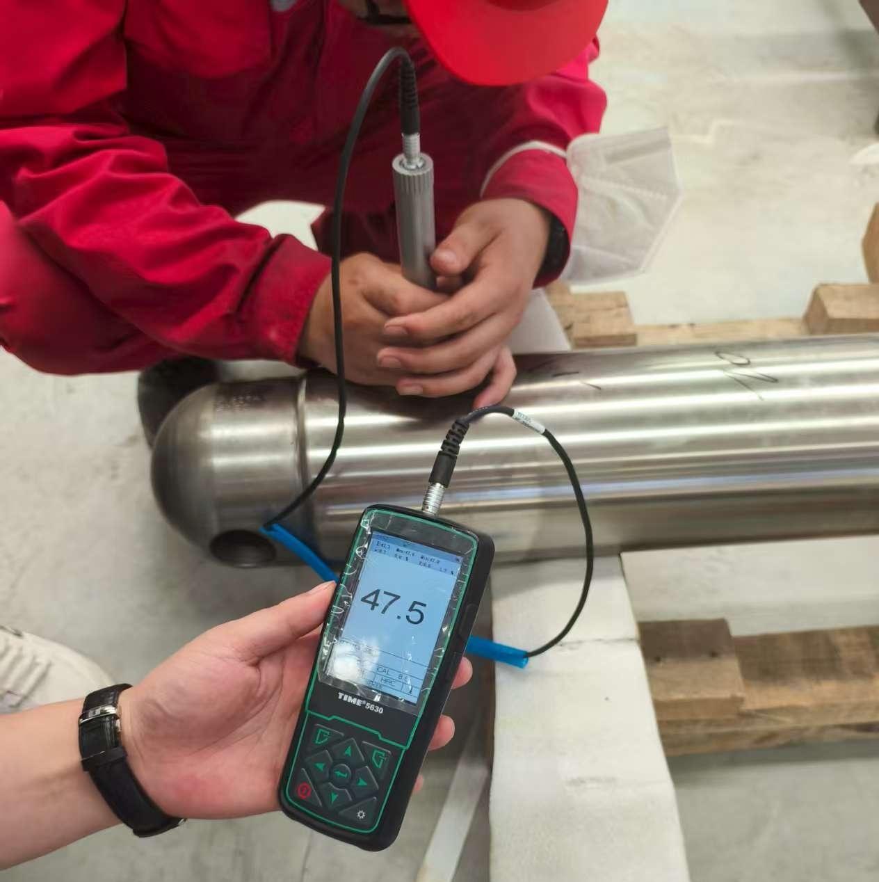
Ultrasonic hardness testing (UCI method), with its micron-level indentation and dynamic testing principles, has become the preferred solution for non-destructive hardness evaluation of laser cladding.
I. Technical Principle: Innovative Design of Ultrasonic Hardness Testers
Core Working Mechanism
Dynamic Indentation Response:
A diamond indenter (136° Vickers) generates micro-vibrations (amplitude approximately 1μm) under 20kHz ultrasonic excitation. This indentation, applied with an extremely light load (1-10N), penetrates the material surface, creating a micro-indentation with a depth of only 2-20μm.
Hardness Conversion Model:
Hardness values are negatively correlated with the indenter vibration frequency attenuation. By measuring the resonant frequency offset Δf, the Vickers hardness (HV) or Rockwell hardness (HRC) can be directly converted:
HV = K · (1 / Δf)^2 (K is the instrument calibration factor)
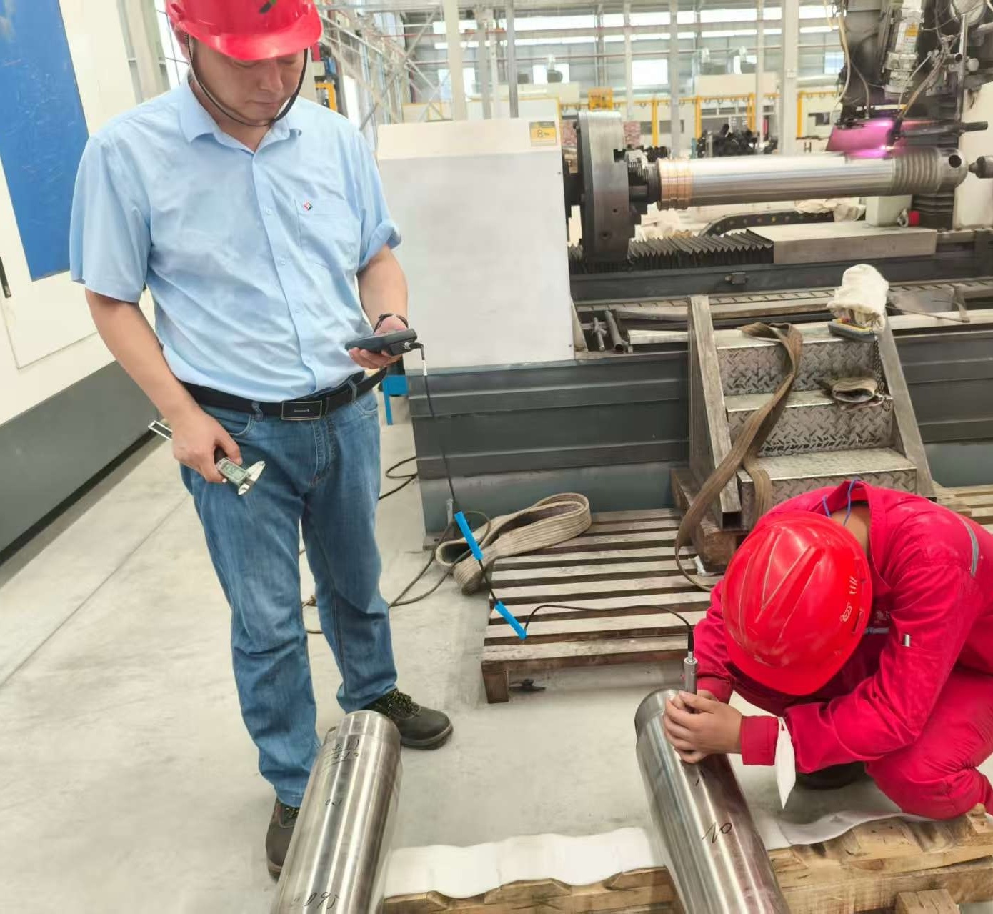
II. Practical Breakthroughs in Laser Cladding Hardness Testing
Precise Gradient Hardness Mapping
Taking the inspection of a nickel-based alloy (Inconel 625) cladding layer on a gas turbine blade as an example:
Data Value:
Surface Hardness: HV 580 ± 15 (corresponding to HRC 54)
Transition Zone (0.3mm): HV 420 → Substrate HV 260
Determination of Heat-Affected Zone (HAZ) Range: 0.25-0.35mm
III. Expanded Application Scenarios
1). Additive Manufacturing (3D Printing) Quality Control
Challenge: Difficulty accessing internal support structures of titanium alloy printed parts;
Solution: Use a 90° right-angle probe to measure the hardness of the overhanging surface, with an error control within ±3%.
2) Heat Treatment Carburized Layer Depth Assessment
- Traditional Limitation: Specimens must be cut for metallographic examination.
- Ultrasonic Solution: Inferring the carburized layer depth using the hardness gradient curve (e.g., the carburized layer boundary is where the hardness drops to 1.2 times that of the substrate). Correlation with metallographic methods reaches R²=0.97.
IV. Future Trend: Intelligent Hardness Cloud Platform
AI Defect Prediction: Automatically identify defects such as lack of fusion and porosity based on hardness distribution cloud maps (with an accuracy rate >92%);
Digital Twin Integration: Real-time hardness data is fed back to the cladding process system, dynamically adjusting laser power and powder feed rate.
Ultrasonic hardness testers, through minimally invasive testing and dynamic response technology, solve the industry's challenges in laser cladding hardness evaluation.
With the in-depth application of intelligent algorithms, they are evolving from a single detection tool to a core sensor for cladding process optimization, providing full-lifecycle hardness data support for high-end manufacturing.
-
Phone: +86-10-62966798
Fax: +86-10-62980728
Email: export@timegroupndt.com.cn


